Chibi Circuitz
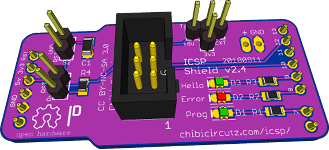
Arduino as ICSP programming shield.This is a DIY project where you can buy the parts and solder up an ICSP programming adapter for use with your Arduino. ICSP (in-circuit serial programming) or ISP (In-system programming) is used on many micro controllers including most Arduino boards so this adapter should provide you with lots of options as you design your circuits.


Background
When researching how to program an external device via ICSP there were quite a few designs floating around to utilize Arduino as an ICSP or ISP programmer. Since none of the ones I found really felt right to me at the time, I started designing a version for my needs.
There was a really cool asymmetrical design that caught my eye while searching for examples and it became the primary inspiration for this project. The MEGA-ISP Shield by Yaroslav Osadchyy, uses Pin Through Hole (PTH) components and gave me several design elements to improve on. The first was to make the board outline symmetrical so it both; looks good and feels right when plugging it in to Arduino. Next, since I was transitioning from PTH devices to Surface Mount Devices (SMD) at the time and I wanted to minimize PCB vias; all of the transitions from the top layer to the bottom layer are done at the PTH headers.
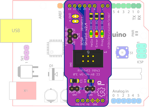
After hearing about issues with ICSP programmers due to the variety of Arduino and compatible boards out there and the differences in how boards automatically reset, the two jumpers; J1, and J2, were added to provide two different options to help resolve any auto reset issues that you may come accross. I have not yet needed to use these, but those options are there just in case.
I have been using various iterations of this ICSP programmer for a while now and this is the most recent version of my ICSP shield for Arduino.

ICSP Shield V2.4 Features:
- Uses ArduinoISP sketch provided with Arduino.
- Power target device from Arduino (5v or 3v3 lines) or external power connection with jumper to select.
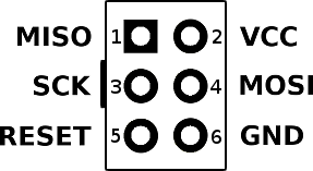
- 6 pin standard ICSP header footprint provided to interface with most products supporting ICSP.
- Jumper select for reset hold or override so you can customize to your Arduino environment.
- Partial shield format with pinout to match original Arduino Duemilanove (Uno or other compatible Arduino) shield layout.

Arduino pins and use
| Digital IO | Description |
| 7 | Programming in process - LED |
| 8 | Error with programming - LED |
| 9 | Heartbeat/Hello - LED |
| 10 | Target Reset |
| 11 | MOSI |
| 12 | MISO |
| 13 | SCK |
*Gnd is common between Arduino host and slave device.
*External power, Arduino 3v3 or Arduino 5V are selectable by jumper to power Slave device.
Pin assignments are already done in the ArduinoISP sketch.
Parts list for assembly
| Part | Value | Package |
|---|---|---|
| C1 | 10uF | 1206 |
| D1 | Green | 0805 |
| D2 | Red | 0805 |
| D3 | Green | 0805 |
| R1 | 330 Ohm | 0805 |
| R2 | 330 Ohm | 0805 |
| R3 | 330 Ohm | 0805 |
| R4 | 120 Ohm | 0805 |
Construction notes
When inserting the boxed 6 pin header, note that pin one (1) has an octagonal pad while pin six (6) is square in order to denote the location of the ground pin; follow the silk screen orientation when placing the polarizing notch of the boxed header if that connector is chosen.
The optional external power input was designed for a two pin JST type header. The right angle JST headers that I had in stock are oriented with the wire connection going across the board when mounted on the top of the board or going off the side when mounted below the board. This may vary with the connectors you source. The external power can also be accomplished by using a two pin screw terminal block or two more generic snapable header pins.
OSH manufactures the PCB to order so there is about two weeks lead time on these. Also note that you need to order in multiples of three and remember to set up your account before ordering in order to save time.


 Home
Home
